MEMS1049 — Spring 2026
Team 27 — James Puzon, Tom Kisiel, Sean Savidge
| Feature | Mechatronic Element |
|---|---|
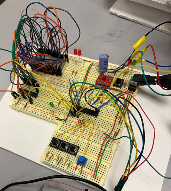
| Feeder automatically dispenses food portions | Stepper motor |
| "Feed Now" button triggers feeding cycle | Interrupt |
| Dispensing timing control | Delay |
| Bowl food level check | Analog measurement |
| Feeding time display | 4× 7-segment displays |
| 7-segment control | MAX7221 driver |
| 12V to 5V conversion | Voltage regulator |
| Time-setting and control inputs | 3× push buttons |
| Power status indicator | LED |
| Pre-feed activity indicator | LED (blinking) |
| Weight sensor activity indicator | LED |
| Enabled feeding-time indicators | 2× LEDs |
| Portion size adjustment | Potentiometer |
| Reservoir empty detection | Force sensor |
| Reservoir empty warning | Software-controlled LEDs |
The primary dispensing actuator is a stepper motor. It rotates in 90° increments to move a paddle wheel and dispense repeatable portions of food from the reservoir into the bowl.
For analysis, the interaction between the paddle and food is modeled as an equivalent drag/friction force on one paddle face.

Variable form
n = Nrev / tdispense
Where:
n: required rotational speed (rev/s)Nrev: revolutions needed to dispense one full portion (rev)tdispense: desired dispensing time (s)Numeric form
n = 2.5 rev / 5 s = 0.5 rev/s
0.5 rev/s × 60 s/min = 30 RPM
Using Newton's second law for rotation:
ΣM = Iα
Summing moments about the shaft axis (CCW positive):
τMotor - FDrag · r = Iwheel · α
Estimated paddle-wheel inertia (plastic, ~20 g, R ≈ 0.02 m), approximated as a solid disk:
Iwheel ≈ (1/2) mR² ≈ (1/2)(0.02)(0.02)² ≈ 4×10⁻⁶ kg·m²
Worst-case angular acceleration (0 to 30 RPM in ~0.1 s):
αmax ≈ π rad/s / 0.1 s ≈ 31 rad/s²
Inertial torque:
Iα ≈ (4×10⁻⁶)(31) ≈ 1.3×10⁻⁴ N·m ≈ 0.013 N·cm
This is approximately 0.25% of the calculated resistance torque, so inertia is neglected (α ≈ 0):
τMotor = FDrag · r
The paddle moves through granular food, so FDrag is modeled as Coulomb friction:
Wfood = mfood · g
FDrag = μfood · Wfood
Where μfood ≈ 0.5 (estimated kibble-plastic friction coefficient). This is an estimate; testing can refine it.
τMotor,req = SF · FDrag · r
Using SF = 2 to account for:
Numeric form
Wfood = 0.496 kg · 9.81 m/s² = 4.87 N
FDrag = 0.5 · 4.87 = 2.44 N
r = 0.8 in = 0.0203 m
τMotor,req (no SF) = 2.44 · 0.0203 = 0.0495 N·m = 4.95 N·cm
τdesign = 2 · 4.95 = 9.9 N·cm
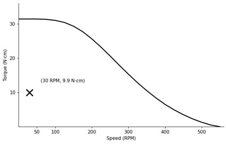
Motor: Pololu #1200 (SOYO SY42STH47-1206A)
Vrated = Irated · Rcoil = 1.2 × 3.3 = 3.96 V ≈ 4 V
Selected driver: Pololu A4988 Stepper Motor Driver Carrier